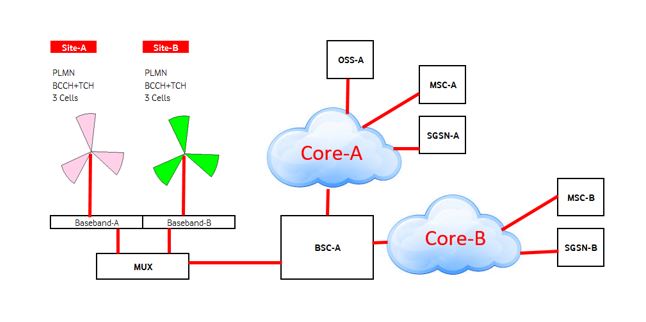
ICR- Intra Circle roaming is sharing of network of one operator with another operator.
The main aim of ICR is to expand coverage in new locations.
There are two types of ICR. Normal ICR and Spider ICR.
ICR can be done on circle basis. E.g. if Operator-A do not have License (2G, 3G or 4G) in a circle (e.g. Assam, Pune or any circle) then Operator-A can provide 3G network
In that particular circle by doing an ICR agreement with Operator-B which is having operating license in that circle.
On site wise basis Operator-A will take ICR service from Operator-B where Operator-A doesn’t have its footprint.
The above 2 cases we consider as Normal ICR.
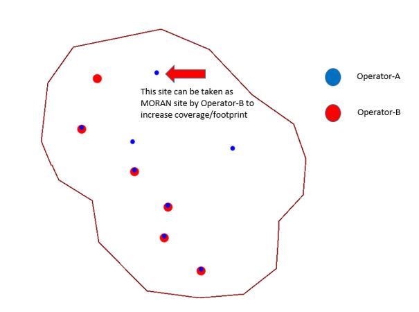
There is a third scenario where in a same town both Operator-A and Operator-B have coverage.
To improve coverage in the black hole locations we can do ICR in between the two Operators.
Such type of ICR is called Spider ICR
Normal ICR:
Normal ICR has two possibilities-
- Network level ICR
- Site wise ICR
Network Level ICR:
Telecom circles are divided based on geography. E.g. in India there are 23 telecom circles like Assam, North East,UP East, UP West, Kolkata, West Bengal, Pune, Maharashtra etc.
Telecom operators are like Airtel, Idea, Vodafone, RJio, BSNL, AT&T etc.
In network level ICR, suppose Operator-A doesn’t have license of a particular network service, e.g. 3G in all circles or in some circles.
If one telecom Operator-A doesn’t have license in all circles or in 2, 3 circles then they can take ICR from another Operator-B which is having 3G License in all circles or in those particular circles where Operator-A doesn’t have License.
This type of ICR is easy to implement.
We don’t need to do any new configuration for such kind of ICR.
Operator-B has to open all the LACs (Location area code) of all 3G sites (or 2G or 4G sites) for Operator-A. Then any customer of Operator-A moves to an area where Operator-B has 3G coverage, that customer will automatically latch to the network of Operator-B and will get full 3G services.
Even he will not feel any kind of difference from service point of view.
Sometimes he may require to latch to the network manually or by restarting the mobile if visits to a new circle.E.g. one customer visits from Kolkata to Pune.
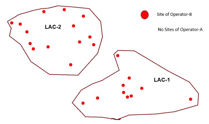
In this scenario both LAC-1 and LAC-2 of Operator-B can be open to Operator-A.
Site wise ICR:
In site wise ICR, network service is shared in some locations where one operator doesn’t have coverage and one is having existing coverage.
If Operator-A doesn’t have coverage in a particular location and Operator-B is having existing network, then Operator-A can take ICR from Operator-B in that particular locations.
In this case Operator-B may need to redefine its LAC based on requirement of sites.
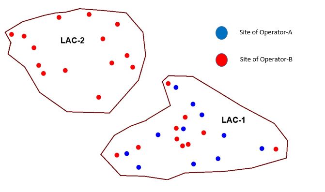
In this case we can open LAC-2 of Operator-B to Operator-A to provide ICR service to the customers of Operator-A. All sites under LAC-2 will provide ICR services.
In the above picture we have seen that Operator-A doesn’t have any sites nearby the LAC-2. So we can offer sites under LAC-2 for ICR purpose.
In some cases we may recreate new LACs based on requirement of sites from the seeker operator (Operator-A in this case).
Spider ICR:
Suppose in a town Operator-A and Operator-B both have their own sites and having coverage.
In some points or locations inside the town there is possibility that in some locations Operator-A is having good coverage but Operator-B doesn’t and vice versa.
In that case both operator can come into an ICR agreement which is called Spider ICR.
Operator-A and Operator-B both will access network of each other and will have a good coverage without any coverage hole if combined spreading of coverage of the two Operators is good.
If a subscriber of Operator-A is roaming inside that town he will latch to the site either of Operator-A or Operator-B based on received signal strength.
Whose signal strength is better based on that subscriber will latch to the sites of that Operator.
This method is very much successful in case of 2G.
But for 4G, practically it shows many difficulties, which finally leads to low data consumption in comparison to No-ICR situation. When 4G Spider ICR reverts to NO-ICR zone, data consumption again takes up its pace as it was earlier.
There is no issue with 2G spider ICR and it works very fine.

In this case LAC-Operator-A is open for Operator-B and LAC-Operator-B is open for Operator A.
A subscriber can access network of both operators continuously without any interruption.
LAC – TAC Mapping:
2G-3G LAC Mapping:
In case of 2G or 3G we only require mapping of LAC. LAC mapping is simple. If a seeker operator is asking for some sites from provider operator and those sites are falling
In some existing LACs and they asked for all the sites of that LAC then the process become very simple and we just have to open those LACs for seeker operator.
Suppose an existing LAC has 50 sites,seeker operator asked for all 50 sites then provider operator just need to open the LAC for the seeker.
If seeker operator is asking for 30 sites for ICR then we have to create new LAC for those 30 sites and remaining 20 sites will have separate LAC. The new LAC created for 30 sites will make open for the seeker operator.
Before creating new LAC we have to properly check whether the LAC formation can be properly done or not and it should not impact badly on PSR (Paging Success Rate) KPI.
Moreover during LAC creation we should take care of highway or major roads. So that due to wrong creation of LAC customers should not go into ping-pong effect, i.e. jumps between 2 LACs continuously which is a wastage of network resource.
4G TAC and 3G/2G LAC Mapping:
In 4G we have to create TAC (Tracking area code) boundary to provide 4G ICR to a seeker operator.
TAC corresponds to the Routing Area (RA) used in Wideband Code division Multiple Access (WCDMA) and GSM/ Edge Radio Access network (GERAN).
TA (Tracking Area) consists of a cluster of RBSs having the same Tracking Area Code (TAC). The TA provides a way to track UE location in idle mode.
If seeker operator is asking for 4G ICR then it should have 3G or 2G network within that area for CS fall back(Circuit switch fall back).
It means during 4G connection it is purely packet switched (only data). So to generate or receive call (circuit switch) it requires CS environment.
If 4G network is having VoLTE (Voice over LTE) services and the subscriber is having VoLTE enable handset then till the time he is in 4G coverage area he can talk in 4G network only.
No need to jump to 3G or 4G network until and unless he is out of 4G coverage area and enters into 3G/2G network area where the operator doesn’t have 4G services.
For CS fall back we require TAC- LAC mapping.
TAC-LAC Mapping Principle
- One or multiple TACs can be part of one LAC
- Multiple LACs can’t be part of one TAC
Now we can take 2 practical scenarios.
Scenario 1:
Provider Network: Provider networks operates on 2G, 3G and 4G
Seeker Network:Operates only on 2G. Seeking ICR for both 3G and 4G.
In this case TAC of 4G of provider,first have to mapped to LAC of 3G of provider and finally to LAC of 2G of seeker network.
Then CS fall back will first happen to 3G network from 4G network and if 3G is also not available then finally to 2G network of the seeker.
These settings/mapping have to done site wise.
If in one site provider does not have 3G network then mapping should be such that CS fall back will directly happen to 2G instead of 3G.
Any subscriber’s mobile will not search for 3G if it latch to such site. It will directly search for 2G network from 4G network.
If 4G site is VoLTE enable and subscriber is also having VoLTE enabled handset then no need of CS fall back.It will operate on 4G network only.
Scenario 2:
Provider Network: Provider networks operates on 2G, 3G and 4G
Seeker Network: Doesn’t have any network. Seeking ICR for 2G, 3G and 4G.
If seeker Operator neither have 4G nor 2G/3G network in a particular location then it requires both 4G as well as 3G/2GICR from provider network.
In this scenario only 4G ICR can’t suffice all requirements.
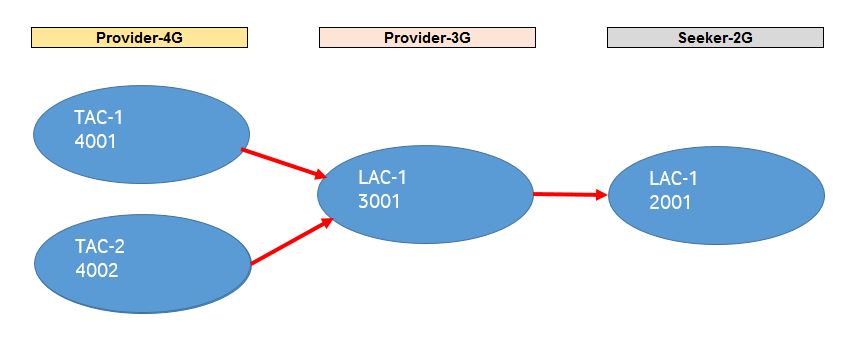
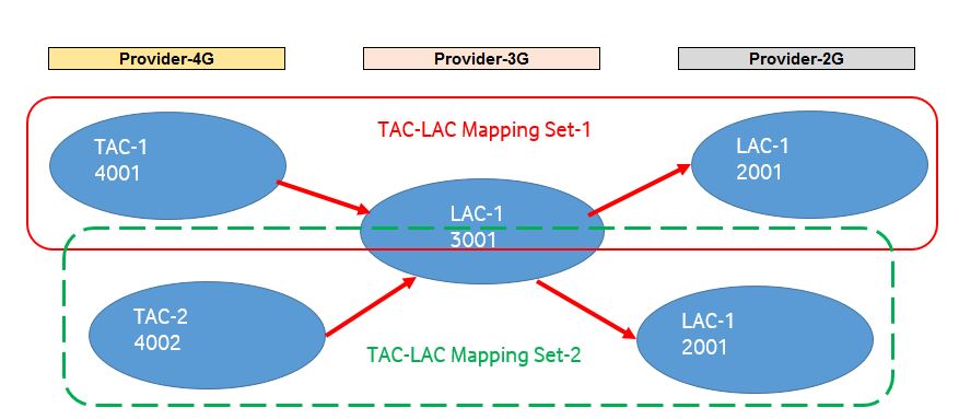
In this case if we do the mapping as like showing in the below mentioned diagram, i.e. 2 4G LACs mapped to 1 3G LAC and then that 3G LAC mapped to 2, 2G LACs then TAC-LAC-Mapping-Set-1 will supersedes TAC-LAC-Mapping-Set-2 and 2nd set of mapping will not work.
So for that either we have to separate one 3G LAC to 2 separate LACs or the 2 LACs of 2G need to combined to 1 2G LAC.
Both arrangement will work properly.
Revenue of Provider from the Seeker operator:
How provider operator would get revenue from the seeker operator it’s totally depends on the agreements between the two operators.
There may be 1, 2 cases.
- Site to site basis– here seeker operators has to provide a minimum amount per site per month e.g. 12K per site until some threshold traffic level.
After crossing the threshold level of the allowed traffic cost will be calculated based on traffic usage in addition to the monthly charges.
If traffic of the seeker network goes high revenue of the provider network also goes high.
- Take and Give-here both operators come to an agreement that both will provide ICR to each other same no of sites in different locations depending on which operator is dominant in which location. In this case no monetary benefit to anyone from each other, but coverage footprint will increase for both operators.
So through ICR agreement an operator can expand its coverage footprint in new areas without any involvement of CAPEX.